Step 0: Pre-Autopsy Pictures
 |
| Front view of the Technics SH-9017 equalizer. |
 |
| Close up of the controls for the left channel. Allows the user to manually change the amplitude of certain frequencies. |
 |
| Back of the equalizer. Note the left has spots for 4 audio connections- line in, line out, tape rec out, and tape playback. |
 |
| Bottom of the equalizer. |
Step 1: Removing the Metal Casing
The metal casing was held on by a few screws, depicted below.
 |
| One screw was on either side of the metal casing. |
|
 |
| 4 screws were on the back of the metal casing. There were two along the top rail as shown here and one on either side rail. |
 |
| Once those screws were removed, the top of the metal casing came off quite easily! |
Step 2: Looking Inside the Black Box
 |
| To our surprise, the box was practically empty. There were a total of 4 PCBs, and they did not take up even half of the volume of the box. The equalizer was probably this size to make it look more impressive and make it easier to stack with other home theater equpiment (such as a receiver and DVD player). |
Step 3: Removing the Main Equalizer PCB
 |
| The front panel was attached to the bottom of the equalizer box with a few screws. |
 |
| Once the screws were removed, the front black panel came off quite easily. However, some electrical components were still attached to it. |
 |
The power button circuit was
unscrewed from the front panel. |
 |
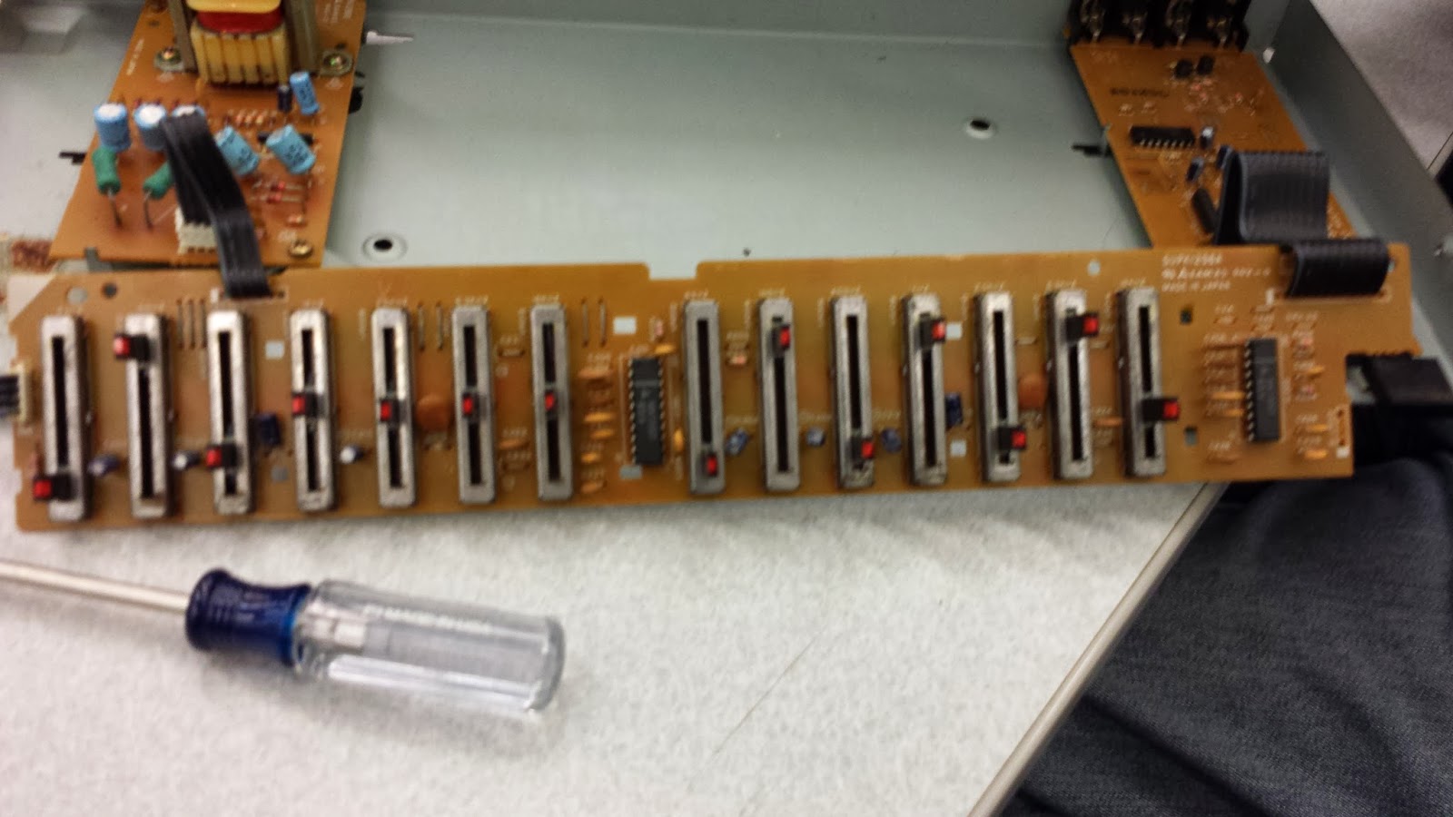
| The long, skinny PCB was clipped to the black plastic with a few pins. |
 |
| Unclipping the black pins shown in the previous picture freed the circuit board. |
 |
| At this point, most of the circuitry is removed from the casing. |
Step 4: Removing Remaining Screws and Disconnecting Ribbons
 |
| The other two circuit boards were screwed down to the metal bottom, so these screws were removed. |
 |
| Circuit board was unscrewed from the bottom. |
 |
| The boards were connected with ribbon cables. A small screwdriver was used to free the cable from the connector. |
 |
| The power supply circuit was popped off from the back panel with a screwdriver. |
 |
| Once the power supply was removed, all of the circuitry was taken apart as much as possible. |
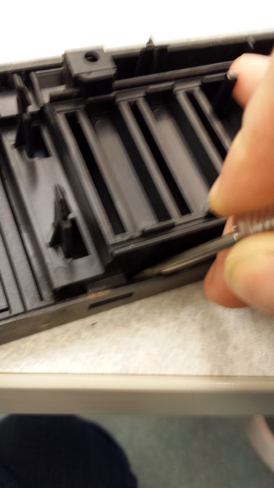
Step 5: Taking Apart Plastic Bits (From Front of Casing)
 |
| Power supply plastic popped out of back of casing. |
 |
| Plastic bits removed from bottom of casing. |
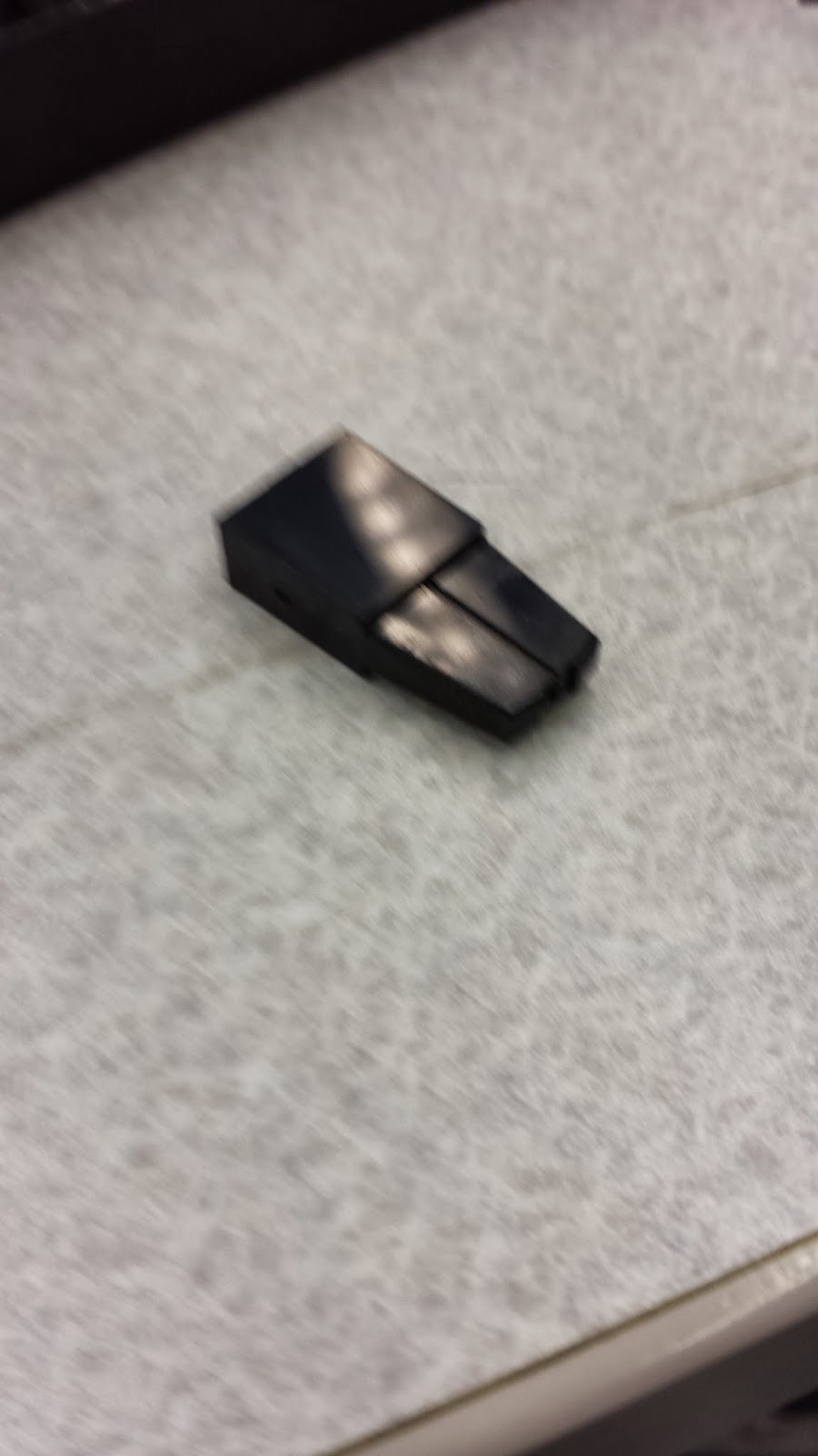
The front panel consisted of two panels snapped together, with little plastic bits used as sliding knobs to control the dB gains.
Step 6: Final Look at PCBs


Power Button circuit, front and back.
Main equalizer circuit board. All of the "magic" goes on here.
 |
| Circuit that controls which input/output is being used. |
 |
| It is a beautiful hand drawn circuit board. |
The power supply connector, front and back.
 |
| Power circuit. Converts power to something usable for other parts of the circuit. |
.jpg) |
| This also has a beautiful hand drawn back. |
Step 7: All of the Parts!


No comments:
Post a Comment