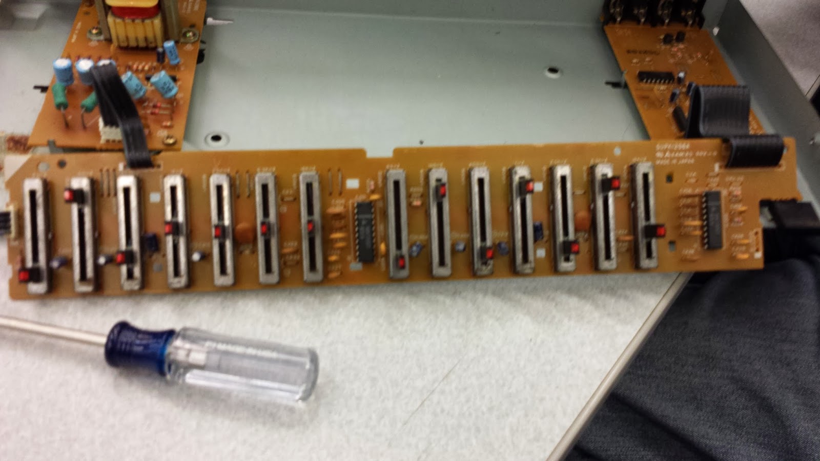
There were a few interesting components of the system's mechanical design. Specifically, the slide potentiometers and the overall casing bear particular discussion.
The potentiometers were designed to have inset LEDs. This way a user could look at the equalizer from a fair distance away, and graphically see the approximate shape that the frequency-gain graph should have. However, more interesting than that is the middle of the pots: there is a small "hiccup" in the middle of each slider, so that they will try to "click" into place at exactly 1/1 gain. Of course, it is possible to fine tune each slider near the center, but most users will likely want to reset some frequency bands to neutral, making this click a necessity.
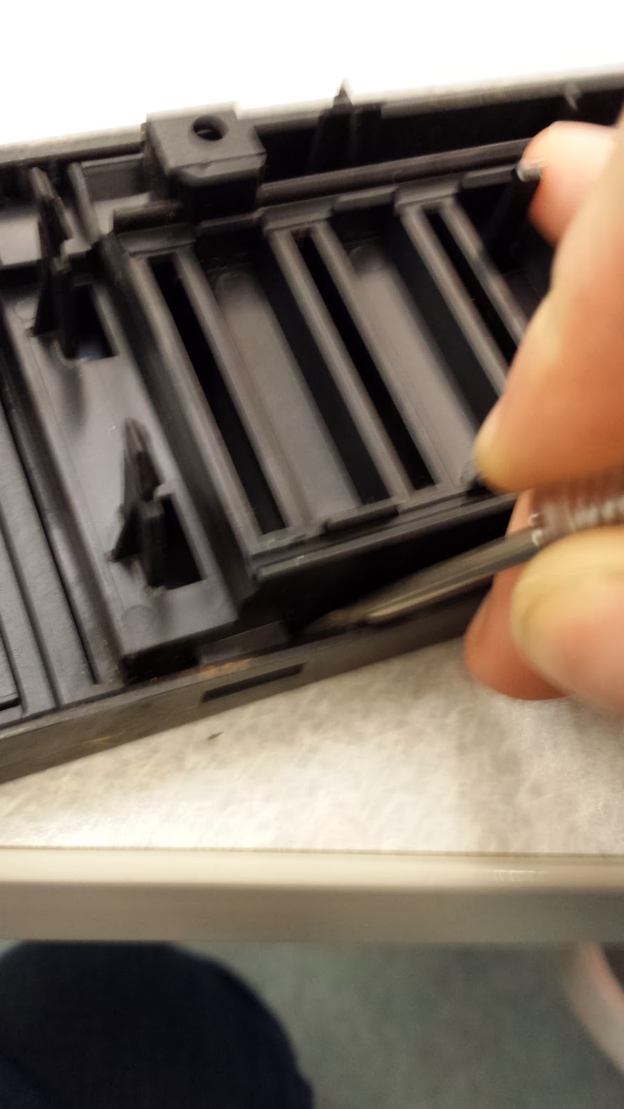
The casing was at first a confusing design to look at. Upon opening the large casing for the equializer, we discovered that there were a few small circuit boards, and a lot of empty space sitting around. In fact, the vast majority of the insides were unfilled. We wondered what purpose this could possibly serve, until we realized the general use of one of these equalizers: it would probably live in a stack of audio equipment, tape decks, speakers, and so on. In order to stack nicely, the equalizer would have to be fairly large and sturdy in order to support several more pieces of equipment above it.
Graphic Equalizer Autopsy
Tuesday, January 28, 2014
Bill of Materials
| Part Number | Manufacturer | Part Description | Quantity | Link to Data Sheet |
| NJM4559S | New Japan Radio Company, Ltd. (JRC) | Dual op-amp, +/- 4-18V supply voltage, 100dB voltage gain, 5MΩ input resistance, ~3.5mA operating current | 1 | Link |
| LC4066B | Sanyo Semiconductor | Quad analog switch. When control input is H, resistance between 70Ω and 300Ω from input to output; when control input is L, resistance is >1GΩ. Operating range ~5V-15V. | 1 | Link |
| NL354522 | Mitsumi | Transformer | 1 | (Could not be located) |
| AN7337 | Panasonic | 7-element graphic equalizer IC for Hi-Fi audio equipment | 2 | Link |
| No part number found. | 45mm 100KOhm Slide Potentiometer w/Red LED | 14 | ||
| 2SC1740S | Secos | NPN Plastic Encapsulated Transistor | 1 | Link |
| ST2SA933 | Semtech Electronics | PNP Silicon Epitaxial Planar Transistor/td> | 1 | Link |
| 2SC2878 | Toshiba | NPN transistor; high-emitter base voltage 25V; high reverse hFE=25; low on resistance=1Ω | 2 | Link |
| SSHK75 | Panasonic | Push-switch; juts out when off, sets in when on. | 1 | Link |
| No part number found. | Red-and-white 4-plug audio I/O ports | 2 |
System Block Diagram
The device was remarkably simple. The power source was sent through a transformer and a series of capacitors in order to filter it down to the power supply needed for the individual chips on the board. When the device was powered and an audio signal was sent into Line In, the signal was sent through an equalizer IC which divided the signal into various wavelengths. Each one of these wavelengths was sent through a voltage divider, where the user was able to change one of the resistances via the sliding knobs on the front of the device, therefore changing the gain for that wavelength. Finally, all of the signals were MUXed and sent to Line Out.
Pictures Showing Disassembly, Insides
Step 0: Pre-Autopsy Pictures
 |
| Front view of the Technics SH-9017 equalizer. |
 |
| Close up of the controls for the left channel. Allows the user to manually change the amplitude of certain frequencies. |
 |
| Back of the equalizer. Note the left has spots for 4 audio connections- line in, line out, tape rec out, and tape playback. |
 |
| Bottom of the equalizer. |
Step 1: Removing the Metal Casing
The metal casing was held on by a few screws, depicted below.
 | |
|
 |
| 4 screws were on the back of the metal casing. There were two along the top rail as shown here and one on either side rail. |
 |
| Once those screws were removed, the top of the metal casing came off quite easily! |
Step 2: Looking Inside the Black Box
Step 3: Removing the Main Equalizer PCB
 |
| The front panel was attached to the bottom of the equalizer box with a few screws. |
 |
| Once the screws were removed, the front black panel came off quite easily. However, some electrical components were still attached to it. |
 |
| The power button circuit was unscrewed from the front panel. |
 |
| The long, skinny PCB was clipped to the black plastic with a few pins. |
 |
| Unclipping the black pins shown in the previous picture freed the circuit board. |
 |
| At this point, most of the circuitry is removed from the casing. |
Step 4: Removing Remaining Screws and Disconnecting Ribbons
 |
| The other two circuit boards were screwed down to the metal bottom, so these screws were removed. |
 |
| Circuit board was unscrewed from the bottom. |
 |
| The boards were connected with ribbon cables. A small screwdriver was used to free the cable from the connector. |
 |
| The power supply circuit was popped off from the back panel with a screwdriver. |
 |
| Once the power supply was removed, all of the circuitry was taken apart as much as possible. |
Step 5: Taking Apart Plastic Bits (From Front of Casing)
 |
| Power supply plastic popped out of back of casing. |
 |
| Plastic bits removed from bottom of casing. |
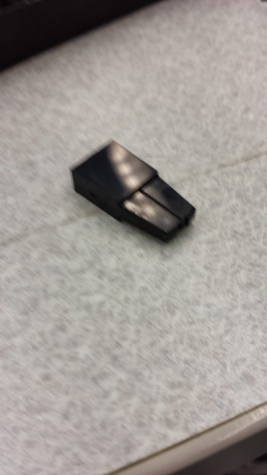
The front panel consisted of two panels snapped together, with little plastic bits used as sliding knobs to control the dB gains.
Step 6: Final Look at PCBs


Power Button circuit, front and back.
Main equalizer circuit board. All of the "magic" goes on here.
 |
| Circuit that controls which input/output is being used. |
 |
| It is a beautiful hand drawn circuit board. |
The power supply connector, front and back.
 |
| Power circuit. Converts power to something usable for other parts of the circuit. |
.jpg) |
| This also has a beautiful hand drawn back. |
Step 7: All of the Parts!
Test Results Showing Operation
Unfortunately, we weren't able to get our equalizer to work -- it had some funky plugs, and besides that, it looked like some of the components were likely burned out. However, we did get a video of the mechanical interface in use.
And not to be discouraged by such unimportant things as a non-working system, we were able to locate another video by someone with a probably younger system, appropriately displaying its functionality.
Each slider corresponds to some frequency band. When the equalizer is turned off, the audio is ported straight through from IN to OUT. When it is turned on, a gain is applied to each frequency band, proportional to the slider's position. (In fact, the reason this is called a "graphic equalizer" is that the LEDs on the sliders resemble a plot of frequency against gain.)
User Manual
We did manage to find the user manual... but, unfortunately, you need to pay to download it. There are a few pages available online, but the quality is not the best. Luckily for us, there were not too many parts in the equalizer so we did not require the service manual to figure out how it worked.
Introduction
We are Sean Lowen and Greg Edelston, two students at Olin College in Needham, MA. For one of our classes this semester, EE Prototyping, we were assigned to perform an "autopsy" on a piece of commercial electronics: disassemble it, take pictures, study its construction, and figure out roughly how it works.
We chose to study the Technics SH-8017, a graphics equalizer produced by Panasonic in the early 1980s. In the following posts, you can find our deconstruction and brief and analysis of the equalizer. (In general, the narrative reads from bottom to top, but can really be read in any order.) Enjoy!
Subscribe to:
Comments (Atom)


